Single Phase Energy Meter (Notes) single-phase-energy-meter_nptel
{Please click on above link}
The principle of working and construction of induction type meter is very simple and easy to understand that’s why these are widely used in measuring energy in domestic as well as industrial world. In all induction meters we have two fluxes which are produced by two different alternating currents on a metallic disc. Due to alternating fluxes there is an induced emf, the emf produced at one point (as shown in the figure given below) interacts with the alternating current of the other side resulting in the production of torque. 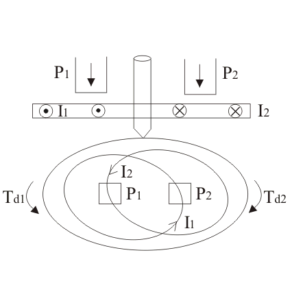 Similarly, the emf produced at the point two interacts with the alternating current at point one, resulting in the production of torque again but in opposite direction. Hence due to these two torques which are in different directions, the metallic disc moves.
Energy meters are the basic part to measure the power consumption. It is used everywhere, no matter how big or small consumption it is. It is also known as watt-hour meter. Here we discuss the construction and working principle of induction type energy meter.To understand the structure of watt-hour meter, we must understand the four essential components of the meter. These components are as follows:
- Driving system
- Moving system
- Braking system
- Registering system
Single phase induction type energy meter consists of four important systems which are written as follows:
1.Driving System
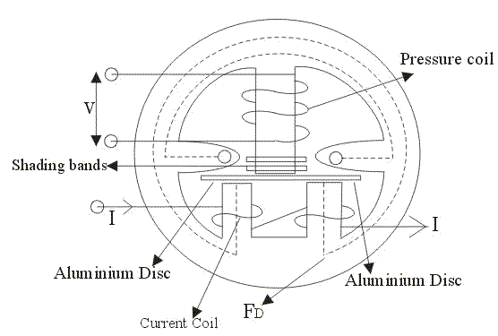
Driving system consists of two electromagnets on which pressure coil and current coils are wounded, as shown above in the diagram. The coil which consisted of load current is called current coil while coil which is in parallel with the supply voltage (i.e. voltage across the coil is same as the supply voltage) is called pressure coil. Shading bands are wounded on as shown above in the diagram so as to make angle between the flux and and applied voltage equal to 90 degrees.
2. Moving System
In order to reduce friction to greater extent floating shaft energy meter is used,the friction is reduced to greater extinct because the rotating disc which is made up of very light material like aluminium is not in contact with any of the surface. It floats in the air. One question must be arise in our mind is that how the aluminium disc float in the air? To answer this question we need to see the constructional details of this special disc, actually it consists of small magnets on both upper and lower surfaces. The upper magnet is attracted to an electromagnet in upper bearing while the lower surface magnet also attracts towards the lower bearing magnet, hence due to these opposite forces the light rotating aluminium disc floats.
3. Braking System
A permanent magnet is used to produce breaking torque in single phase induction energy meters which are positioned near the corner of the aluminium disc.
4. Counting System
Numbers marked on the meter are proportion to the revolutions made by the aluminium disc, the main function of this system is to record the number of revolutions made by the aluminium disc.
Working Principle of Energy Meter
The working of single phase induction type energy meters are based on two main fundamentals:
- Rotation of aluminum disk.
- Arrangement of counting and displaying the amount of energy consumed.
Rotation of an Aluminum Disk
The rotation of metallic disk is operated by two coils. Both the coils are arranged in such way that one coil produces a magnetic field in proportion to voltage and the other coil creates a magnetic field proportion to current. The field produced by voltage coil is delayed by 90° so that eddy current is induced in the disk. The force exerted on the disk by the two fields is proportional to the product of the immediate current and voltage in the coils.
As a result of it, a lite weight aluminum disk rotates in an air gap. But there is a need to stop a disk when there is no power supply. A permanent magnet works as a brake which opposes the rotation of the disk and balances the speed of rotation with respect to power consumption.

Arrangement of Counting and Displaying the Energy Consumed
In this system, the rotation of the floating disk has been counted and then displayed on the meter window. The aluminum disk is connected to a spindle which has a gear. This gear drives the register and the revolution of the disk has been counted and displayed on the register which has series of dials and each dial represent a single digit. There is a small display window in the front of the meter which displays the reading of energy consumed with the help of dials. There is a copper shading ring at the central limb of the shunt magnet. To make the phase angle between flux produced by shunt magnet and supply voltage about 900, small adjustments in the place of the ring is required. 
Please Click here for
Video 1: Single Phase Energy Meter
Video 2 : See below
Video 3 : Working of a practical electromechnical energy meter
Happy Learning !!!

sir the video is not three dimensional.the concept is not made clear
LikeLike
Please refer notes (single phase energy meter nptel) uploaded recently for more clarification .
LikeLike
I liked the summary on the working principle of the meter. Could someone please give more ellaboration on the driving torque however?
How does eddy current flow in the disk without an external circuit?
LikeLike